

Introduction:
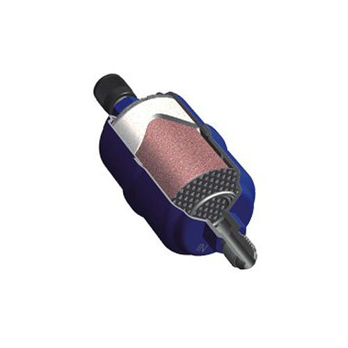
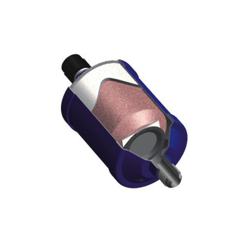
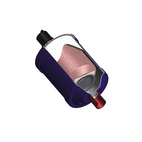
The check valve uses magnetic attraction to return the valve diaphragm to its seat instead of spring. A conventional type check valve requires an increase pressure to force the valve pedestal off its seat,this easy cause increasing pressure drop. The magnetic check valve (MCV) has a decreasing force to move it away from its seat and it use the magnetic attraction to a decrease the pressure drop more. MCV’s are therefore a more higher efficient option than the conventional check valves.
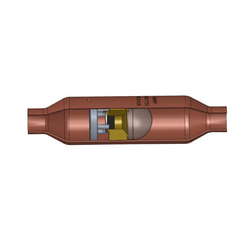
The check valve uses the latest technology in magnetic diaphragm, a manufacturing method that eliminates the use of braze materials that can overheat and damage internal components. The body is 100% copper that has been spun into shape and the connections machined. The result is a valve that is hermetically sealed, can easily be installed with either soft or hard solder, with a almost zero leak rate, suitable for used in the Liquid, Suction, Discharge or Hot Gas line used fluorinated refrigerants, these valves are ideal in a new installation or as a replacement for conventional check valves. MCV’s are not recommended for Heat Reclaim applications with high differential pressures.
Feature:
1.Multi orientation while maintaining flow direction
2.Hermetic spun copper body design
3.Designed for maximum flow and minimal pressure drop
4.Valve diaphragm coated with Neoprene
5.Built-in 30 mesh stainless steel screen
6.Copper connection sizes 1/4”through 3-1/8”
7.Stable,Zero leak
8.Negligible loss in system efficiency
9.Efficient sealing with a negligible leak rate
10.Able to be installed in any position
11.Filt function to extend the valve service life
12.Suitable for a wide range of applications, including combination (muffler/check valve)
Technical Performance :
Safe working pressure 5.2MPa up to 5/8” sizes
Working temperature range: -40℃~+130℃
100% leak testing
Compatible with all CFC, HCFC and HFC refrigerants and oils
|
Cross Reference (Identical Lay-In) |
|||
|
HangF |
Emerson |
HenryTech |
Superior |
|
8114-04 |
ACK-4 |
MS-04 |
900M-4S |
|
8114-06 |
ACK-06 |
MS-06 |
900M-6S |
|
8114-08 |
ACK-08 |
MS-08 |
900M-8S |
|
8114-10 |
ACK-10 |
MS-10 |
900M-10S |
|
8114-12 |
ACK-12 |
MS-12 |
900M-12S |
|
8114-14 |
ACK-14 |
MS-14 |
900M-14S |
|
8114-18 |
ACK-18 |
MS-18 |
N/A |
|
8114-22 |
ACK-22 |
MS-22 |
N/A |
|
8114-26 |
ACK-26 |
MS-26 |
N/A |
|
8114-34 |
ACK-34 |
MS-34 |
N/A |
|
8114-42 |
ACK-42 |
MS-42 |
N/A |
|
8114-50 |
ACK-50 |
MS-50 |
N/A |
|
Model |
Connector |
Shell Body C |
Length B |
Mesh No. |
SWP(F^>a) |
(cm3/sec) Leakage Rate@420kPa |
Kv(m3/Hr) |
|||||||||||||||||||
|
8114-04 |
1/4 |
22 |
102 |
30 |
5500 |
<0.00025 |
0.47 |
|||||||||||||||||||
|
8114-06 |
3/8 |
22 |
102 |
30 |
5500 |
<0.00025 |
0.99 |
|||||||||||||||||||
|
8114-08 |
1/2 |
22 |
102 |
30 |
5200 |
<0.00056 |
0.99 |
|||||||||||||||||||
|
8114-08B |
1/2 |
29 |
127 |
30 |
5200 |
<0.00056 |
2.67 |
|||||||||||||||||||
|
8114-10 |
5/8 |
22 |
102 |
30 |
5200 |
<0.00056 |
2.98 |
|||||||||||||||||||
|
8114-10B |
5/8 |
29 |
127 |
30 |
5200 |
<0.00056 |
2.98 |
|||||||||||||||||||
|
8114-12 |
3/4 |
29 |
127 |
30 |
4100 |
<0.00123 |
5.56 |
|||||||||||||||||||
|
8114-12B |
3/4 |
41 |
178 |
30 |
4100 |
<0.00123 |
5.56 |
|||||||||||||||||||
|
8114-14 |
7/8 |
29 |
127 |
30 |
4100 |
<0.00123 |
7.58 |
|||||||||||||||||||
|
8114-14B |
7/8 |
41 |
178 |
30 |
4100 |
<0.00123 |
7.58 |
|||||||||||||||||||
|
8114-18 |
1-1/8 |
41 |
213 |
30 |
4100 |
<0.00203 |
13.19 |
|||||||||||||||||||
|
8114-18B |
1-1/8 |
54 |
213 |
30 |
4100 |
<0.00203 |
13.19 |
|||||||||||||||||||
|
8114-22 |
1-3/8 |
54 |
213 |
30 |
4000 |
<0.00287 |
16.26 |
|||||||||||||||||||
|
8114-26 |
1-5/8 |
54 |
213 |
30 |
3000 |
<0.00453 |
27.78 |
|||||||||||||||||||
|
8114-34 |
2-1/8 |
92 |
305 |
30 |
3200 |
<0.00643 |
48.27 |
|||||||||||||||||||
|
8114-42 |
2-5/8 |
105 |
330 |
30 |
3000 |
<0.00853 |
64.76 |
|||||||||||||||||||
|
8114-50 |
3-1/8 |
105 |
330 |
30 |
3000 |
<0.00995 |
80.95 |
|||||||||||||||||||
|
Model |
Connector |
(kW ) Liquid refrigerating capacity |
||||||||||||||||||||||||
|
Liquid line |
Suction Line |
HotGas |
||||||||||||||||||||||||
|
R22 |
R134 |
R404A |
R407C |
R410A |
R507 |
R22 |
R134 |
R404A |
R407C |
R410A |
R507 |
R22 |
R134 |
R404A |
R407C |
R410A |
R507 |
|||||||||
|
8114-04 |
1/4 |
9.5 |
8.8 |
6.8 |
9.7 |
9.8 |
6.7 |
1.1 |
0.8 |
0.9 |
1 |
1.3 |
1 |
4 |
3.2 |
3.8 |
3.9 |
5 |
3.5 |
|||||||
|
8114-06 |
3/8 |
19.9 |
18.3 |
14.2 |
20.2 |
20.5 |
13.9 |
2.2 |
1.6 |
2 |
2.1 |
2.8 |
2 |
8.3 |
6.6 |
7.9 |
8.1 |
10.4 |
7.4 |
|||||||
|
8114-08 |
1/2 |
53.8 |
49.4 |
38.2 |
54.4 |
55.3 |
37.6 |
6.0 |
4.4 |
5.3 |
5.6 |
7.6 |
5.4 |
22.3 |
17.9 |
21.3 |
21.9 |
28 |
19.9 |
|||||||
|
8114-10 |
5/8 |
60 |
55.1 |
42.6 |
60.7 |
61.7 |
41.9 |
6.7 |
4.9 |
5.9 |
6.3 |
8.4 |
6 |
24.9 |
20 |
23.7 |
24.4 |
31.3 |
22.2 |
|||||||
|
8114-12 |
3/4 |
112.2 |
103.1 |
79.7 |
113.5 |
115.3 |
78.4 |
12.5 |
9.2 |
11 |
11.7 |
15.8 |
11.3 |
46.5 |
37.4 |
44.4 |
45.7 |
58.5 |
41.5 |
|||||||
|
8114-14 |
7/8 |
152.8 |
140.4 |
108.5 |
154.6 |
157.1 |
106.8 |
17 |
12.5 |
15 |
16 |
21.5 |
15.4 |
63.4 |
51 |
60.5 |
62.2 |
79.7 |
56.5 |
|||||||
|
8114-18 |
1-1/8 |
265.9 |
244.3 |
188.8 |
269.1 |
273.3 |
185.8 |
29.6 |
21.7 |
26.1 |
27.8 |
37.4 |
26.8 |
110.2 |
88.7 |
105.2 |
108.3 |
138.6 |
98.3 |
|||||||
|
8114-22 |
1-3/8 |
327.9 |
301.3 |
232.8 |
331.8 |
337 |
229.1 |
36.5 |
26.8 |
32.2 |
34.3 |
46.1 |
33 |
135.9 |
109.3 |
129.8 |
133.5 |
170.9 |
121.2 |
|||||||
|
8114-26 |
1-5/8 |
560.1 |
514.6 |
397.7 |
566.8 |
575.7 |
391.4 |
62.3 |
45.8 |
54.9 |
58.5 |
78.8 |
56.4 |
232.2 |
186.8 |
221.7 |
228 |
292 |
207.1 |
|||||||
|
8114-34 |
2-1/8 |
973.3 |
894.3 |
691.1 |
984.9 |
1000.4 |
680.1 |
108.2 |
79.5 |
95.5 |
101.7 |
136.9 |
98.1 |
403.5 |
324.6 |
385.2 |
396.2 |
507.4 |
359.9 |
|||||||
|
8114-42 |
2-5/8 |
1305.9 |
1200 |
927.3 |
1321.5 |
1342.3 |
912.5 |
145.2 |
106.7 |
128.1 |
136.5 |
183.6 |
131.6 |
541.4 |
435.5 |
516.8 |
531.6 |
680.7 |
482.9 |
|||||||
|
8114-50 |
3-1/8 |
1305.9 |
1200 |
927.3 |
1321.5 |
1342.3 |
912.5 |
145.2 |
106.7 |
128.1 |
136.5 |
183.6 |
131.6 |
541.4 |
435.5 |
516.8 |
531.6 |
680.7 |
482.9 |
|||||||
The rated liquid and suction capacities are based on an evaporating temperature: An average temperature of t = -10℃, liquid temperature ahead of the valve t = 25℃ and a pressure drop across the valve of p = 15 kPa (2.18 psi).

 English
 中文简体
中文简体